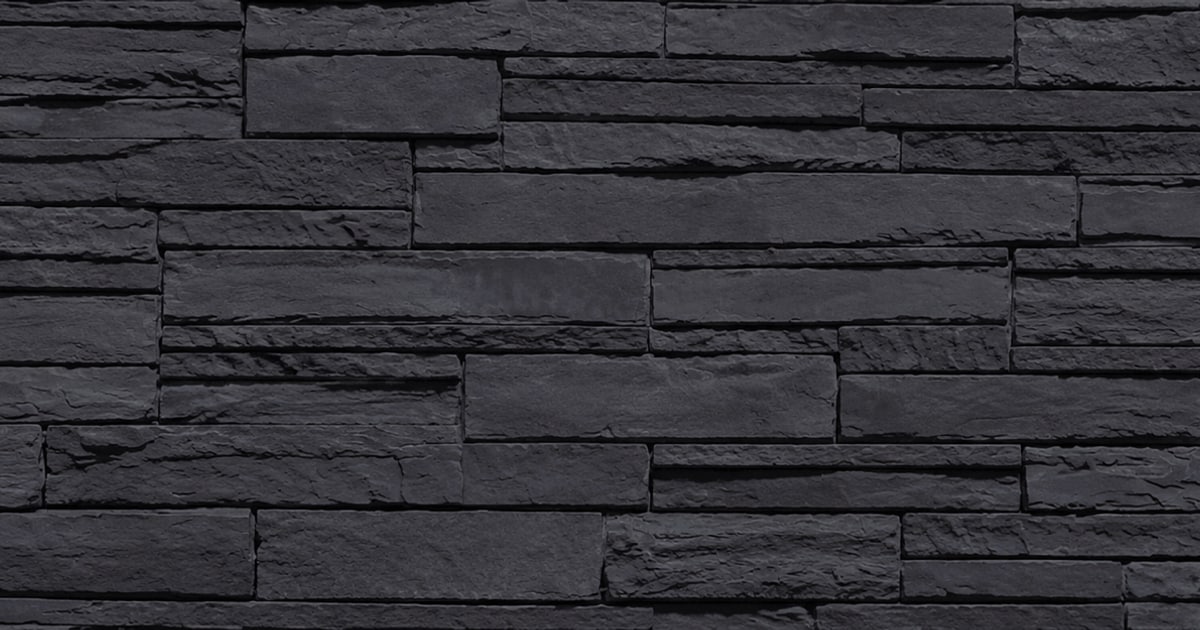
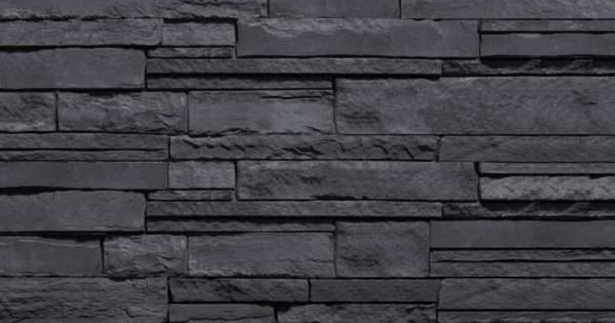
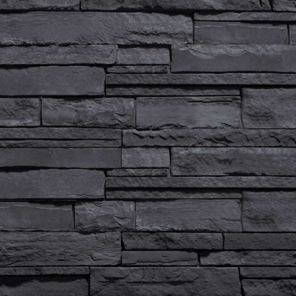
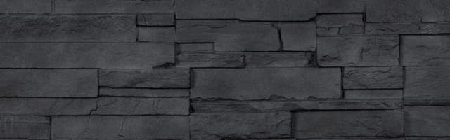
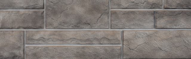
- 1
Building code requirements: building code requirements vary — check with local authorities to determine requirements for your area. Panels are designed for application over wood framing spaced 16" on center, covered by a code-approved nailable sheathing product (minimum 7/16" OSB or ½" plywood). Wall framing should be designed to limit out-of-plane deflection to a minimum of L/240. Testing applies to applications up to 30' in height — installations above 30' must be approved by a design professional. Provide a means for drainage and ventilation at all horizontal terminations (typically achieved using Starter Strip and J-Channel in conjunction with flashing).
- 2
Water Resistive Barrier (WRB): cover sheathing with minimum one layer of Grade D building paper or WRB meeting ICC Acceptance Criteria #38 or ASTM E 2556/E 2556M. Wrap WRB minimum 16" past all inside and outside corners; integrate with all flashing. Do not fasten the bottom 12" of WRB until starter strip installation. Local building code or climate may require 2 layers of WRB.
- 3
Personal protective equipment: safety glasses or goggles (ANSI Z87.1 Grinding Face Shield), NIOSH-approved N-95 series disposable particulate filtering facepiece respirator (required when cutting or grinding — product contains crystalline silica), gloves, ear plugs or muffs, steel toe boots, and hard hat.
- 4
Tools required: hammer, circular saw, hand grinder, chop saw (10" sliding compound miter) or wet saw with continuous diamond turbo blade, level, chalk line, tape measure, pneumatic roofing nail gun (optional), tin snips, 5/16" rod or dowel (optional), brush, small screwdriver. Follow all tool manufacturer's safety instructions.
- 5
Fasteners: corrosion-resistant galvanized roofing nails or screws with head diameter 3/8" minimum and shank 1/8", length sufficient to penetrate framing material minimum 1". Hot-dipped galvanized nails or screws are recommended. Electro-galvanized are acceptable but may exhibit premature corrosion. Important: treated lumber may react with metal or coating of fastener — determine material compatibility when selecting fasteners.
- 6
Before you begin: inspect the installation area — confirm framing is 16" o.c. and sheathing is minimum 7/16" OSB or ½" plywood. Verify WRB, flashing, and caulking are installed or are part of the installation package. Check walls for plumb and square; identify any defects or protrusions and correct them before proceeding.
- 7
Determine your starting point: the product must maintain a clearance of minimum 4" from grade if soil, or 2" if a hard surface (paving or concrete). Mark your starting line as a level line — do not rely on the ground for level. Account for the Starter Strip nailing flange so its bottom lands on your desired starting line. Mark framing locations with pencil or chalk line.
- 8
Starter Strip installation: install perfectly level at your starting point. Fasten with roofing nails or screws every 8"–10" in the center of nail slots — drive straight and do not drive tight (allow 1/32" gap between fastener head and strip). Allow ¼" clearance at material butt joints and ½" at corners and end wall terminations.
- 9
J-Channel installation: install at windows, doors, material transitions, penetrations, and terminations. Fasten every 8"–10" in the center of nail slots. Allow 1/32" gap between fastener head and channel. Allow ¼" clearance at material butt joints. For horizontal applications, drill 3/8" drain holes every 12" in trim channel.
- 10
Panel installation — general rules: install panels bottom to top, lapped in shingle fashion so tongue seats completely into groove. Stagger panels from row to row to avoid alignment of vertical joints. Fasten panels level and plumb — drive fasteners straight and flush. Pull product from multiple boxes as you work to blend any colour variation. Mark level lines every 24" as reference.
- 11
Attaching flat panels: starting at the bottom, position the first panel with nailing flange up and tongue into the Starter Strip. Fasten with a minimum of 4 fasteners in the top nailing flange — at least 2 fasteners must penetrate framing; end fasteners must be within 3" of the panel end. Position the second panel into the Starter Strip and slide to nest end tabs with the edge of the first panel. Continue down the wall repeating this procedure. Before the next course, clean any debris from the first course groove. Each course should have a minimum 8" stagger from the previous course.
- 12
Universal Corner installation: Universal Corner panels must be cut into 2 pieces to create left and right. Ideally cut random lengths to assist with wall stagger — avoid pieces shorter than 8". Each Universal Corner will require a minimum of 2 fasteners when 18" or less, with at least 1 into framing; 4 fasteners when greater than 18", with at least 2 into framing. Alternate left and right ends on each course. Universal Corner panels may be used as outside corners, inside corners, or end wall terminations.
- 13
Cutting and modifications: do not cut more than one panel at a time. Use tools with a continuous diamond turbo blade (table saw or miter saw) for clean cuts. For holes (hose bibs, electrical boxes), use a masonry hole saw, drill, or grinder with a masonry blade. Always wear N-95 respirator when cutting — cutting creates crystalline silica dust. Caution: dusts from cutting or sawing may create possible cancer hazard; avoid prolonged or repeated inhalation.
- 14
Estimating materials: (1) Determine wall area: wall width (ft) × wall height (ft). (2) Subtract area of windows, doors, and any areas not to be covered — this is your net wall area. (3) Flat Panel Area ÷ 2 = number of Flat Panels required. (4) Corner Height (ft) × 1.5 = Universal Corner Coverage; Universal Corner Coverage ÷ 2 = number of Universal Corner Panels. (5) Add a 10% scrap factor. One Universal Corner Panel provides 2 sq. ft. of wall area coverage.